Cirrus Optical Properties, Enhanced version (COPE)
In addition to the single scattering properties in COP, this version
contains:
- the complete 4x4 scattering matrix of hexagonal ice crystals.
- the scattering matrix of imperfect hexagonal ice crystals.
1. The Scattering Matrix
The state of polarization of electromagnetic radiation can completely
be described by the 4 elements of the Stokes vector. The Stokes vector
of scattered radiation is related to that of the incoming radiation by
a 4x4 scattering matrix:

For the present data base, only particles in random orientation are
considered. In this case, the scattering matrix contains only six
independent elements which are not dependent on the scattering azimuth
angle:

These six elements are available in COPE.
2. Imperfect hexagonal ice crystals
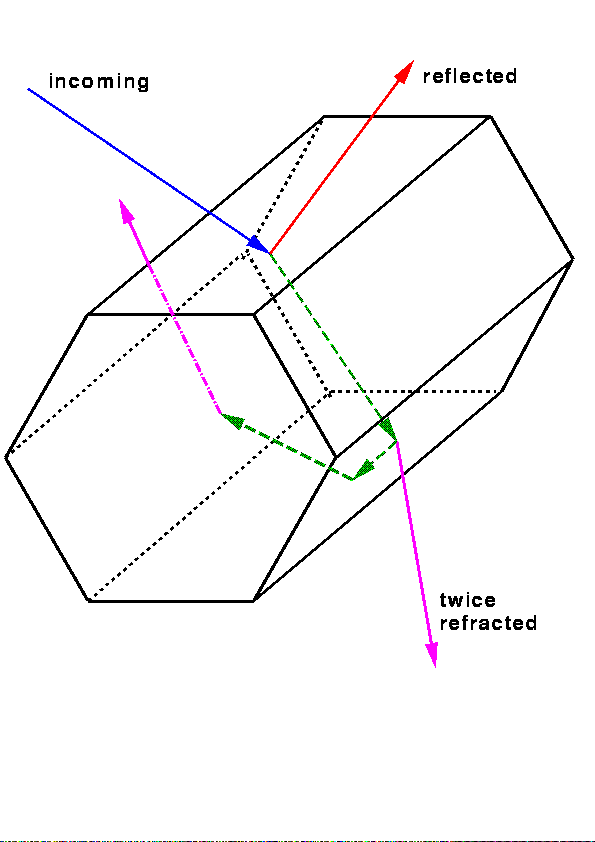
Imperfect hexagons are modelled using statistical deviations of ray
paths during the ray tracing (Figure 1) in hexagonal ice crystals.
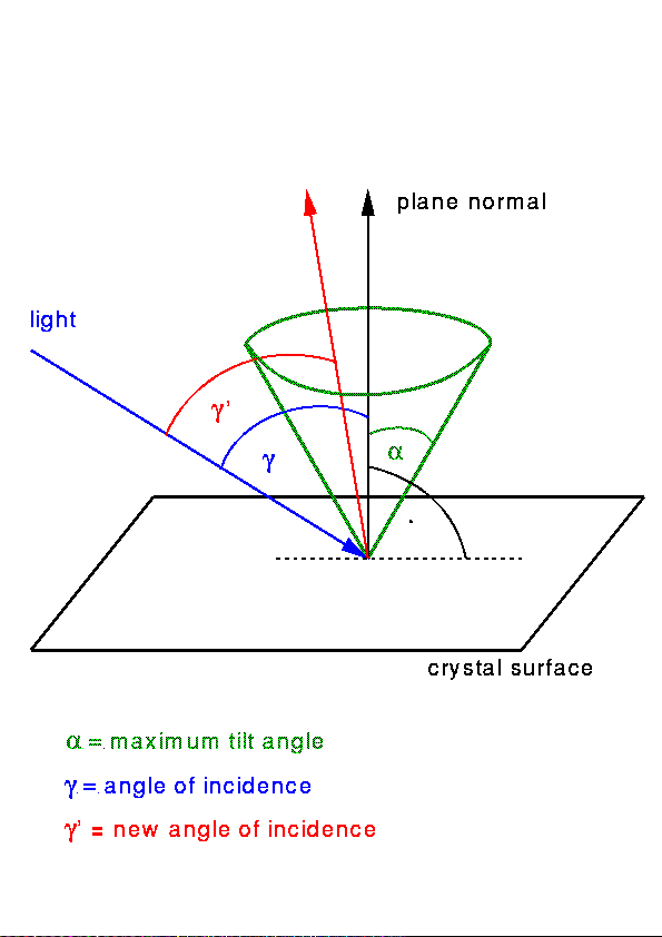
Each time a ray hits a
crystal surface, the normal to this surface is tilted against its
original direction by a certain angle, and it is also rotated around
it (Figure 2). This tilt angle is chosen by use of
random numbers, which are uniformly distributed between 0 and a given
maximum value. The azimuth angle is randomly distributed between 0
and 2*Pi. The directions of the refracted and reflected ray are
calculated according to this tilted surface element.
 |

|
| Figure 1: Ray tracing in a hexagonal column. |
Figure 2: Tilting of plane normals during the ray tracing. |
A maximum tilt angle of 1° only affects the direct forward and
backward scattering. This scattering matrix may better be suited for
lidar applications than the original scattering matrix without any
tilting because the extremely strong increase in the direct
backscattering at 180° does not occur here. A maximum tilt angle
of 30° removes all halo features in the scattering function and
may therefore be a more realistic model of ice crystals in many cirrus
clouds which don't show halos.
3. The data files
The scattering matrices of randomly oriented hexagonal columnar ice
crystals are stored in the directory dat/corr. There is one
file for each scattering matrix. The file names reflect size and shape
of the crystal, the wavelength, and the maximum tilt angle. They
consist of 9 letters (e.g.
c40550r01.cs) with the following
meaning:
- c4 means column No. 4. For the sizes and numbers of
the particles, have a look at the table.
- 0550 means a wavelength of 550 nm.
Currently available
are the wavelengths:
0.550 µm, 0.659 µm, 0.865 µm, 1.6 µm, 3.7 µm.
- r means random orientation.
- 01 is a maximum tilt angle of 1°.
Currently available
are the maximum tilt angles:
0°, 1°, 30°, 90°
These data files contain the following information:
- INPUT parameters for ray tracing:
- length of a-axes and c-axes of the ice crystal
- wavelength
- refractive index
- maximum tilt angle
- OUTPUT of ray tracing:
- extinction, scattering, and absorption cross sections
- single scattering albedo
- asymmetry parameter
- relative amount of unscattered rays (going through two
planparallel faces of the crystal)
- mean geometrical cross section of the crystal
- the scattering matrix elements F11,
F22/F11, F33/F11,
F44/F11,
-F12/F11, F34/F11
There are two additional columns after the matrix elements, which are
related to a scattering matrix test and correction algorithm after
Hovenier and van der Mee (1996).
4. The program cope.f
This program uses results of the ray tracing program for particles of
different sizes to calculate size distribution weighted averages of
the single scattering properties. cope.f relies
on certain conventions about the number of size intervals and the
sizes of the particles (see table). For each
calculation of size distribution weighted scattering properties, the
scattering matrices of the 8 columns must exist for the
desired wavelength. There is also a convention about the composition
of the names of the files (see above).
The currently available contents of the data base is indicated in the
file cope.cfg. This file is read by cope.f to fill in
its selection menus.
Once started, the program asks several questions. This dialog is shown
here.
5. How to get and install COPE ?
You can download COPE from our anonymous ftp server ftp.lrz-muenchen.de
in the directory "pub/science/meteorology/cirrus".
Copy the file cope.tar.gz in a new directory, unzip and untar
it:
> gzip -d cope.tar.gz
> tar -xvf cope.tar
Now, you will see two new subdirectories: cope and dat.
cope contains the program cope.f and all other files
necessary for running it. dat contains the two subdirectories
dat/corr and dat/sums, where dat/corr contains
the scattering matrices of 8 columnar ice crystals for 5 wavelengths
and 3 maximum tilt angles. In dat/sums, the output of the
program cope.f will be stored.
page created by Michael Hess
update: 15. Jan. 1999


